


Unity CV2GIP Installation Guide
Decentralised Mechanical Extract Ventilation (dMEV)
Table of Contents
Important Update for CV2GIP Owners and Specifiers
The popular Greenwood CV2GIP dMEV fan has officially been discontinued by the manufacturer and is no longer in production. Its direct replacement in the Greenwood range is the new CV2.1HT, however, we now strongly recommend the Vent-Axia NBR dMEV fan as the superior modern alternative.
Here’s a side-by-side look at why we believe the Vent-Axia NBR is the better choice for most projects:
Why we now recommend the Vent-Axia NBR over the CV2.1HT
Significantly lower energy use – The NBR routinely achieves 0.15–0.19 W/l/s, making it one of the most efficient constant-volume dMEV fans on the market. This can translate into meaningful savings on electricity bills and easier compliance with Part L and future Building Regulations.
Much quieter operation – In real installations, customers consistently report the NBR as “almost silent” compared to the already-quiet CV2GIP. Perfect for bedrooms, apartments, and noise-sensitive projects.
Longer warranty & EC motor reliability – The brushless DC motor and 7-year warranty give greater long-term peace of mind.
Better humidity control – The NBR uses true proportional humidity tracking (not just a simple on/off humidistat), reducing unnecessary running and condensation more effectively.
Future-proofed – With tightening energy and noise regulations, the NBR’s performance headroom keeps it well ahead of minimum requirements.
Overview
The Greenwood Unity CV2GIP is a continuously running (dMEV) extract fan, designed to offer a simplistic approach to meet Building Regulations and provide an energy efficient domestic ventilation solution to improve indoor air quality in dwellings.
The concept revolves around 'one product', which has been designed to be flexible in application (ceiling and wall installations) and to meet the performance requirements of all 'wet' rooms within a dwelling. The Unity CV2GIP features new Greenwood TimerSMART™ and Greenwood HumidiSMART™ technology (fully automatic integral delay/over-run timer and humidity functions) which monitor the homeowners' environment.
Key Features
- Continuously running dMEV extract fan
- Flexible installation - wall or ceiling mounting
- Greenwood TimerSMART™ technology (automatic timer function)
- Greenwood HumidiSMART™ technology (automatic humidity control)
- Boost speed facility for peak ventilation times
- Suitable for all wet rooms (bathroom, kitchen, WC)
- SAP Appendix Q certified
- Easy commissioning with control panel
Package Contents
- 1x Unity CV2GIP Unit
- 1x Loose item set (screws and fixings)
- 1x Installation Instructions
- 1x User/Homeowner Guide
Ancillary Items Required (Not Included)
- 100mm round ducting or Flat duct (110 x 54mm) or (204 x 60mm)
- 100mm external grille
- Appropriate boost switch - Greenwood Airvac GS2 recommended
Installation Instructions
General Preparation
The Unity CV2GIP fan is supplied with a 100mm nominal spigot for connection of ducts for installation. 100mm diameter rigid duct should be used to provide the best performance levels required for compliance with Building Regulations.
The unit can be installed on a wall or ceiling mounted and ducted. The unit must be securely mounted using all four fixing holes provided on the back plate.
Important: Use the No.8 screws provided and ensure all four fixing points on the back plate are securely fitted.
Wall Mounting Installation
Determine the most ideal location for the unit for this installation, taking account of the electrical services. Ensure there is adequate access for installation and eventual replacement.
Note: The electronics cover has been designed to retain and hold screws for ease when positioning/mounting the product to a surface.
1 Remove Outer Front Cover
Rotate the outer front cover to the left until retaining clips are released. Then loosen the 3 fixing screws.
2 Open Electronics Cover
Carefully open the electronics cover until retention hinge is fully extended.
3 Prepare Wall Duct Opening
Cut the duct to width of the plasterboard or tiled wall with slight fall to exterior. Make provisions for electrical cable entry.
4 Secure Fan to Wall
Fill in any gaps with mortar or foam and make good internal and external walls. Make sure that ducting remains circular.
5 Correct Control Panel Orientation
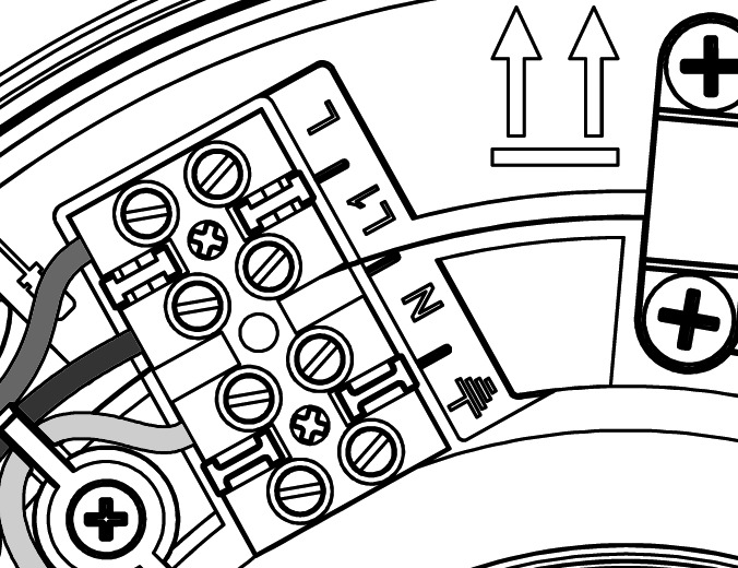
To ensure the control panel is in the correct configuration, mount the fan with orientation symbol arrows facing upwards.
6 Mount and Wire Unit
Using the four No.8 screws, secure fan body to the wall. The electrical cable passes through as appropriate. Wire fan according to wiring instructions.
7 Close Electronics Cover
Carefully close the electronics cover, ensuring that the outer rubber seal edges are positioned correctly back into the fan body.
8 Reattach Front Cover
Tighten the 3 fixing screws. To attach the outer front cover, rotate to the right, utilising the guidance rail, until firmly secured by the retaining clips.
9 Install External Grille
Screw the protective wall grille over the external duct opening.

Ceiling Mounting Installation
The ceiling mounting process follows similar steps to wall mounting, with key differences in positioning and duct routing. Determine the most ideal location for the unit taking account of the electrical services and ensure adequate access for installation.
1 Remove Outer Front Cover
Rotate the outer front cover to the left until retaining clips are released. Then loosen the 3 fixing screws.
2 Open Electronics Cover
Carefully open the electronics cover until retention hinge is fully extended.
3 Cut Ceiling Opening
Cut an opening through the ceiling for the fan and electrical cable.
Dimensions: Ø = 105mm, X = 65mm (depth from ceiling surface)
4 Secure Unit to Ceiling
The unit must be securely mounted using all four fixing holes provided. Wire fan according to wiring instructions.
5 Connect Ducting
Place flexible or rigid ducting over the spigot of the fan. Fit ducting to spigot using appropriate method (refer to section Ducting Guidelines).
6 Close Electronics Cover
Carefully close the electronics cover, ensuring that the outer rubber seal edges are positioned correctly back into the fan body.
7 Reattach Front Cover
Tighten the 3 fixing screws. To attach the outer front cover, rotate to the right, utilising the guidance rail, until firmly secured by the retaining clips.
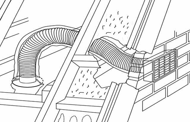
Typical Ceiling Installation Configurations

Activating Smart Features
Greenwood HumidiSMART™
Press the humidity sensor button to activate the Greenwood HumidiSMART™. The light should come on to indicate that the function is active. This feature automatically monitors humidity levels and adjusts ventilation accordingly.
- Factory Default: OFF
- Options: ON / OFF
Greenwood TimerSMART™
Press the timer button to activate the Greenwood TimerSMART™. The light should come on to indicate that the function is active. This feature provides automatic delay/over-run timing for boost operation.
- Factory Default: OFF
- Options: ON / OFF
Ducting Guidelines
A 100mm nominal diameter spigot is provided for connection to ducting. Ductwork should be securely connected to fan spigot. Failure to do this will cause unnecessary air leakage and may impair performance.
Connection and Sealing
All duct connections require sealing. Where ducts are installed against a solid structure this can be difficult to achieve. In such locations preassembly of duct sections should be considered. This will require that connections are permanent to ensure the seal is maintained during installation.
⚠️ Fire Dampers
If applicable, Fire dampers MUST BE FITTED in accordance with Part B of the Building Regulations.
Rigid Ducting
Install using the least number of fittings to minimise resistance to airflow. Where access to ducts will not be possible after construction is complete (i.e. within floor and wall voids), consideration should be given to permanent connection and sealing with an appropriate non-hardening sealant, and not using duct tape to achieve connection and sealing.
Flexible Ducting
Ensure ducting lengths are kept to minimum and ducting is pulled taut so that it is smooth and straight. Where bends are necessary, and where ducting is run in restricted areas, ensure the ducting is not crushed. Connection of lengths of flexible duct must use a rigid connector and jubilee clips or similar to ensure a long term seal is achieved. Connection of lengths of flexible duct should not be taped-only.
External Termination Requirements
The fan exhaust must terminate to external air and be protected by a suitable wall or roof terminal. Roof terminal to have a minimum equivalent free area of 7,500mm².
Electrical Installation
⚠️ Electrical Safety Warnings
- All wiring must conform to BS7671: IEE Wiring Regulations
- The appliance must be isolated from the mains supply before removing the electronics cover
- The installation must be carried out by a qualified electrician
Technical Specifications
| Specification | Value |
|---|---|
| Supply Voltage | 220-240V ~ 50Hz |
| Phase | Single phase (1Ph) |
| Fuse Rating | 3A |
| Maximum Power Consumption | 5 Watts |
| IP Rating | IPX4 |
| Cable Sizes (Maximum) | Fixed flat wiring 2 core 1mm², 3 core 1/1.5mm² |
| Insulation Class | Double insulated (no earth connection required) |
Isolation Switch Requirement
A double-pole switch having a minimum contact separation of 3mm must be used to provide isolation for the unit.
The recommended alternative 'switch-live' switch for use is the Greenwood Airvac GS2 switch.
GS2 Remote Switch Functions
| Switch Position | Function |
|---|---|
| Position I (Trickle) | Fan running at trickle speed (continuous low ventilation) |
| Position II (Boost) | Fan running at boost speed (high ventilation rate) |
⚠️ Heat Source Clearance
The fan must not be mounted above or closer than 1m to the cooker where it could be affected by excessive heat or moisture.
Performance Characteristics
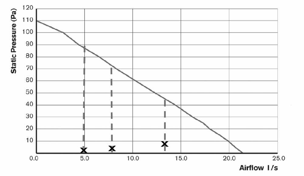
The Unity CV2GIP features automatic compensation for fluctuations in back pressure to meet Building Regulation requirements. The performance graph shows airflow characteristics across different static pressure levels.
Performance Notes
Manual airflow volume settings can be adjusted during commissioning to achieve required performance levels. Default factory settings are marked on the performance curve and represent typical through-wall installation performance.
The fan will automatically compensate for system resistance to maintain the set airflow rates within its operating range.
Wiring Instructions

Wiring Procedure
- Strip cable to correct lengths as shown in the wiring diagram
- Insert cable through cable entry point (A), and then clamp cable using the cable clamp (B)
- Push the wires into the terminal block (C) as per wiring diagram
- Tighten screws of the terminal connection
Note: A facility to park the earth cable has been provided (D). As the fan is double insulated, no connection to earth is required.
Complete Wiring Diagram

The wiring diagram shows the complete electrical installation including:
- 220-240V ~ 50Hz mains supply
- Double-pole isolating switch
- Light switch (for boost activation)
- Fan terminal connections
- Fused spur at 3A
On Site Commissioning and Setup
This section covers setup, configuration of the unit for installation and altering pre-set factory settings.
Control Panel Overview
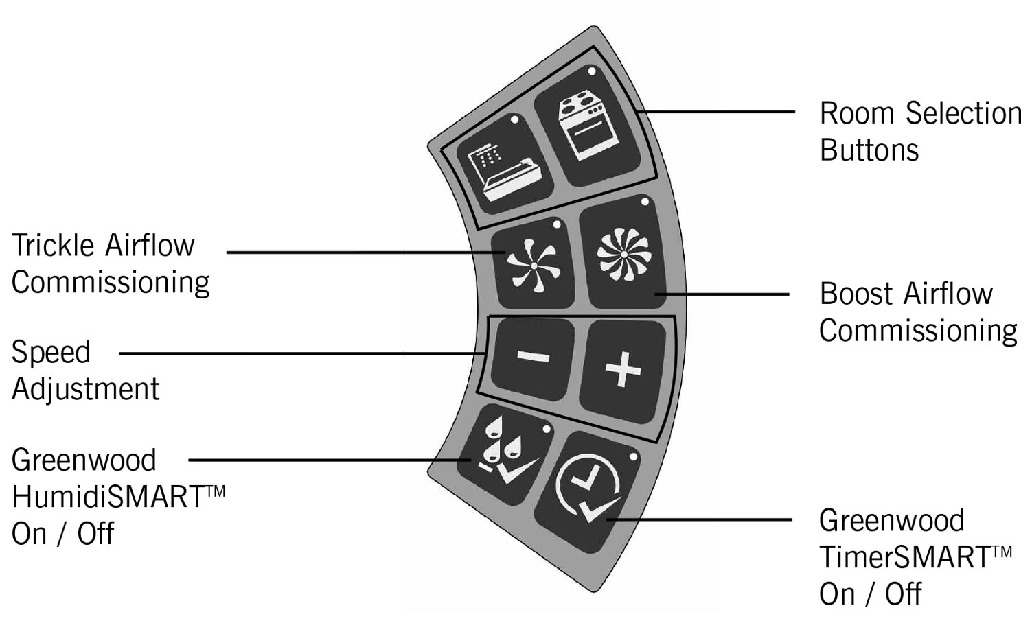
The control panel features the following controls:
- Room Selection Buttons - Choose between Bathroom or Kitchen settings
- Speed Adjustment Buttons (+/-) - Increase or decrease airflow rates
- Trickle Airflow Commissioning Button - Set continuous low speed
- Boost Airflow Commissioning Button - Set high speed for peak times
- Greenwood HumidiSMART™ Button - Enable/disable automatic humidity control
- Greenwood TimerSMART™ Button - Enable/disable automatic timer function
Initial Power-Up and Room Selection
1 Once the wiring connections have been checked, switch the mains supply on.
2 On first power up, both Bathroom and Kitchen room selection button lights should flash to indicate that an appropriate installation setting needs to be selected.
Important: If no button is selected within 15 minutes, the system will automatically default to Bathroom settings and lock out the commissioning section of the controls. To reactivate commissioning mode, see instructions below.
Commissioning Bathroom Fan Airflow Rates (Includes WC)
1 Select Bathroom Mode
Whilst both room selection lights are flashing, press the Bathroom button. The Bathroom light should show as solid.
2 Set Boost Airflow
The Boost speed light should now start to flash.
Boost Factory Setting: 8 l/s (Through Wall)
To adjust the airflow, press the [-/+] buttons to the required level and verify with an airflow measuring device, then press the Boost button to confirm. The 'boost' light should show as solid.
Note for WC Installation: Reduce Boost airflow to 6 l/s for WC applications.
3 Set Trickle Airflow
The Trickle speed light should now start to flash.
Trickle Factory Setting: 5 l/s (Through Wall)
To adjust the airflow, press the [-/+] buttons to the required level and verify with an airflow measuring device, then press the Trickle button to confirm. The 'trickle' light should show as solid.
Note: Selection lights should remain on for approximately 10 seconds to enable the setup and status of the fan to be observed and checked, upon which time the commissioning section of the controls should lock.
Commissioning Kitchen Fan Airflow Rates
1 Select Kitchen Mode
Whilst both room selection lights are flashing, press the Kitchen button. The Kitchen light should show as solid.
2 Set Boost Airflow
The Boost speed light should now start to flash.
Boost Factory Setting: 13 l/s (Through Wall)
To adjust the airflow, press the [-/+] buttons to the required level and verify with an airflow measuring device, then press the Boost button to confirm. The 'boost' light should show as solid.
3 Set Trickle Airflow
The Trickle speed light should now start to flash.
Trickle Factory Setting: 8 l/s (Through Wall)
To adjust the airflow, press the [-/+] buttons to the required level and verify with an airflow measuring device, then press the Trickle button to confirm. The 'trickle' light should show as solid.
Reactivating Commissioning Mode
If you need to re-enter commissioning mode after initial setup:
- Press any button to activate the panel. The current fan setup/status should be shown via the panel lights
- To enter commissioning mode, press and hold the [-] and [+] buttons simultaneously for approximately 3 seconds until the Bathroom & Kitchen lights flash
- Room and airflow settings from previous commissioning should be recalled
- Make adjustments as needed following the commissioning procedures above
Master Reset
To perform a complete factory reset:
- Press and hold the [-] and [+] buttons simultaneously for approximately 10 seconds
- All lights will flash to indicate the fan has been reset to factory settings
- The system will then revert to both room selection lights flashing at the start of commissioning mode
- You must then recommission the unit from the beginning
Default Airflow Settings Summary
| Room Type | Trickle Speed (l/s) | Boost Speed (l/s) |
|---|---|---|
| Bathroom (Default) | 5 | 8 |
| WC | 5 | 6 |
| Kitchen (Default) | 8 | 13 |
Note: These are factory default settings for through-wall installations. Airflow rates can be adjusted during commissioning to meet specific Building Regulation requirements for your installation.
Physical Specification
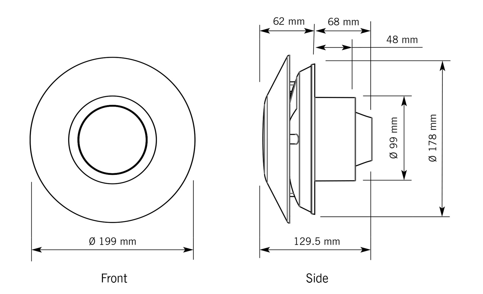
| Dimension | Measurement |
|---|---|
| Front Diameter | Ø 199 mm |
| Backplate Diameter | Ø 178 mm |
| Spigot Diameter | Ø 99 mm |
| Overall Depth | 129.5 mm |
| Spigot Depth | 68 mm |
| Internal Depth | 62 mm |
| Mounting Hole Offset | 48 mm from center |
SAP Appendix Q Compliance
This product features on SAP Appendix Q, which is the UK's system for listing products that meet specific performance criteria for energy efficiency in buildings.
Compliance Requirements
As part of the Building Regulations compliance process, the following steps must be completed:
- Complete the Installation Checklist for dMEV products
- Submit the checklist to building control along with all other relevant paperwork
- Installation checklist is available at: www.sap-appendixq.org.uk
- Record commissioning data using the sheets provided in the User/Homeowner Guide
Important: Record sheets for commissioning information are provided in section 4 of the User/Homeowner Guide supplied with the product. These must be completed by the commissioning engineer and left with the homeowner.
Safety Information
⚠️ Important Safety Notice - Children and Supervision
The appliance is not intended for use by young children or infirm persons unless they have been adequately supervised by a responsible person to ensure that they can use the appliance safely. Young children should be supervised to ensure that they do not play with the appliance.
⚠️ Siting with Fuel-Burning Appliances
Critical Safety Warning: Where an open-flued oil or gas-fuelled appliance is installed in the kitchen, extract ventilation can cause the spillage of flue gases. Care must be taken to ensure ventilation is reduced appropriately, as set out in the Building Regulations.
Kitchens with solid-fuel appliances should NOT have extract fans fitted.
Installation Requirements
- When installing wall mounted fans, ensure that there are no buried cables or pipes in the installation location
- Recommended mounting height: 1.8m above floor level
- Installation must be in accordance with current editions of Building Regulations and BS7671: IEE Wiring Regulations
- Electrical installation must only be carried out by a qualified Electrician
- 100mm diameter rigid duct should be used to provide the best performance levels required for Building Regulations compliance
- Contact Greenwood Airvac Technical Services on +44 (0) 1903 777135 for technical queries
Guarantee Information
This Greenwood product (Unity CV2GIP) comes with a 2 Year Guarantee from the date of purchase.
This guarantee does not affect your statutory rights.